In some applications, such as garage ventilation, fans are designed in parallel. This solution allows only one fan to be operated at low air exchange requirements, and when the air quality sensors are triggered, the second fan can be switched on and the flow rate increased. The above solution has several important conditions, failure to comply with which leads to failure to achieve the required parameters of the equipment, and in worse cases to destruction of the fans.
- The same performance characteristics are a prerequisite for achieving maximum flow and efficiency in the maximum flow range.
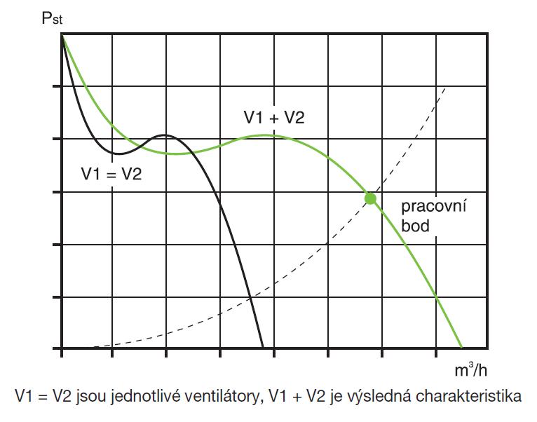
- The operating point must lie in a region close to the maximum flow of the fans (good efficiency region). The operating point must be perfectly known and its position must take into account all possible adverse operating conditions, such as resistance build-up in clogged filter chambers, operational changes in network lengths, etc.
- A working point close to the airflow cut-off point (prohibited area) leads to fluctuation of the working point, strong vibrations and destruction of the impeller. The minimum allowable pressure reserve is 15% below the airflow break-off point.
- Individual parallel branches should be designed to the maximum possible and identical length (resistances must be identical). The distribution of resistances should be as large as possible in parallel branches (minimum 40 % of total resistance) and as small as possible in common branches.
- The separation and connection of pipes shall be made in such a way that the currents interfere minimally. Connecting parallel fans via dampers directly to a common large size duct places extreme demands on damper tightness, damper control and fan actuation. The fans must be separated by tight dampers, otherwise the "false thrust" will cause the impeller of the disconnected fan to spin in the opposite direction and destroy the fan when it is connected to the network by a sensor.
- The fans must be equipped with a suitable soft start control and with a properly designed damper opening control (when the fan starts to run into a closed damper, the fan operates in an unstable non-allowed area). The control circuits must always guard against the situation where improper operation would cause the disconnected fan to spin in the opposite direction (the fan may be spun by short-circuit flow from an operating fan, gravity flow in the duct, etc.). In such cases, control circuits must be used to ensure that the fans are safely stopped and restarted.
- The fan vibration sensor is recommended to be used in cases of important installations as a preventive diagnostic measure. A vibration sensor can help detect bearing failure, fan operation in a restricted area or improper operating point, etc.
Details on the design of paralytic operation of fans can be found in the scripts (CTU FS), the professional monograph Fans / Ing. J. Čermák CSc. 1974, or in other professional publications.
We do not provide any warranty for fans destroyed under the above circumstances.