












 Share on Facebook
 Tweet
 Send email
ELEKTRODESIGN ventilátory spol. s r. o.
Boleslavova 53/15
140 00 Praha 4 – Česká Republika
elektrodesign[zav]elektrodesign[teč]cz
www.elektrodesign.cz
Product description
Functions
The variable air volume (VAV) controller is used for the autonomous control of the volume of ventilated air in a single zone within central ventilation systems.
Design
The VarioflowBOX COMF EVO VAV controller consists of a pair of ducts (supply and extract) fitted with rails for mounting to the supporting structure, an electrical distribution board with a VARIOSU 24-10 power supply unit mounted on the mounting rails of one of the tubes, and a small box containing boost timers (Varioboost 24 VAC). A DIN rail is provided on the electrical distribution board for mounting the Varioboost 24 VAC; alternatively, it can be fitted in the domestic distribution board. Both ducts are fitted with a lip seal for connection to circular ductwork. The individual components are made from galvanised sheet steel. The design differs for the 100 to 160 and 200 to 400 size ranges. In the former, the servo-actuators are located inside the tubes alongside the control dampers, and the air flow is measured using a thermo-anemometer. The second design variant utilises flow measurement based on the pressure differential measured by a probe inside each tube. In this variant, the servo-actuators are mounted on the casing and are fitted with a pressure sensor for air flow. The control dampers located in each of the tubes have a Class 2 tightness rating when closed in accordance with EN 1751, with the exception of the DN 100 version, which is only Class 3.
Electrical
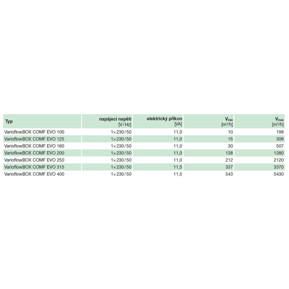
The supply voltage is 1x230 V/50 Hz. The VarioflowBOX COMF EVO is fitted with a 230 V/24 V power supply unit with a connection cable terminated in a 230 V plug with an earth conductor. The air flow rate can be controlled via a 0–10 V analogue signal or two potential-free contacts (BOOSTs). The BOOST function’s run-down time is fixed at 7 or 15 minutes. The regulated air volume in the supply duct is the same as in the exhaust duct (SUPPLY = EXHAUST). The electrical control panel has an IP44 protection rating. The communication interface for the control system can be selected as either Modbus RTU or MP-Bus for sizes 200, 250, 315 and 400. For sizes 100, 125 and 160, only MP-Bus is available.
Installation
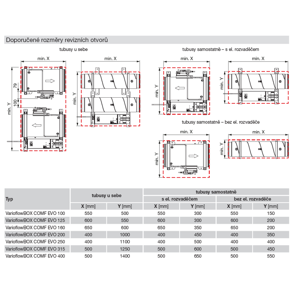
Wall or ceiling mounting with horizontal or vertical airflow directions. It is essential to observe the airflow directions, which are indicated by arrows on the ducts. Sufficient access must be provided to allow for servicing and maintenance of the controller. A straight section of ducting must be provided upstream of the VAV controller in the direction of airflow, before the air enters the tubes, with the following lengths:
• 1x D for DN 100, 125 and 160
• 2x D for DN 200, 250, 315 and 400
Operating conditions
The maximum air flow velocity is 7 m/s for sizes 100, 125 and 160, and 12 m/s for sizes 200, 250, 315 and 400. The minimum air flow velocity is 0.3 m/s for sizes 100, 125 and 160, and 1.2 m/s for sizes 200, 250, 315 and 400. At the manufacturing plant, it is possible to set air flow rate ranges that differ from the standard ranges given in the technical specifications table (the Vmin and Vmax ranges must be specified when ordering). The maximum possible pressure difference across the damper is
900 Pa. The temperature range of the conveyed air should be from 0 °C to +50 °C, and the maximum relative humidity of the flowing air should be up to 95 per cent (condensation on the surface or inside the tubes must be prevented). The air flowing through the ducts must be free from sticky and abrasive particles to prevent clogging of the flow velocity or pressure sensors and the control damper.
Accessories
Wall-mounted controllers are not required for the VarioflowBOX COMF EVO VAV controller. More detailed information on controllers can be found in the ‘Control Options’ section.
• Belimo wall-mounted controllers:
• CRP24-B1
• CRA24-B1P
• CRA24-B3
• ABB wall-mounted controllers:
• Design Zoni
• Design Swing (L)
• Design Tango
• Design Levit (M)
• Design Time (Arbo)
• Design Future linear
• Design Solo (carat)
• Busch-axcent design
• MSKM-KB damper for zoning on the extract air branch (priority extraction from the kitchen)
Adherence to these instructions should not pose any safety, health or environmental risks in accordance with EC directives (CE marked). The same applies to other products used in the device or during installation. Consider the following warnings:
• Observe the safety instructions to prevent damage to the device or personal injury.
• The technical information in this manual must not be changed.
• It is forbidden to interfere with the motor of the device.
• In order for the device to comply with EC directives, the device must be connected to the mains in accordance with the applicable regulations.
• The device must be installed in such a way that under normal operating conditions it cannot come into contact with any moving part and / or live part.
• The device complies with the applicable regulations for the operation of electrical equipment.
• Always disconnect the device from the power supply before carrying out any work on it.
• Appropriate tools must be used when handling or maintaining the device.
• The device must only be used for the purposes for which it is intended.
• This appliance is not intended for use by children under 8 years of age and persons with reduced physical, sensory or mental capabilities, or lack of experience and knowledge, unless they have been given supervision or instruction concerning use of the appliance by a responsible person. The user must ensure that children do not play with the device. Cleaning and maintenance of the appliance must not be carried out by children without supervision.


