
 Share on Facebook
 Tweet
Tweet Send email
Product description
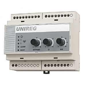
UNIREG is a universal controller designed to control the output of the air handling unit heater depending on the temperature in the room or supply pipe. A 3-point output or a 0-10 V analog output is available. The heater can be:
- hot water - 3-point controlled mixing valve actuator (alternatively a 0-10 V control voltage actuator can be used).
- electric - controlled by a triac switch with a 0-10 V voltage
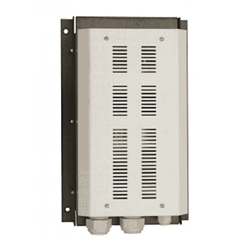
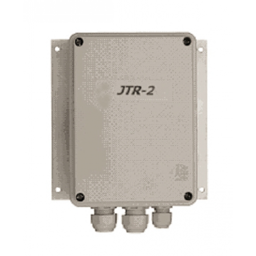
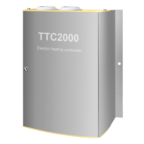
Electric heaters with built-in power section and 0-10 V input can be controlled directly by the controller. Electric heaters without a power part must be connected via a power controller (e.g. JTR 2, JTR 12, JTR 18, JTR 24, TTC 40, TTC 2000).
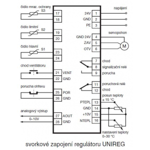
Using the rotary controllers, the user can change the desired temperature, the proportional constant of the controller (cascade factor) and set the minimum supply air temperature for reheating the ventilated space. The desired temperature can also be set remotely. The UNIREG controller functions are selected according to the air handling unit used and the way the sensors are installed by means of miniature switches on the circuit board; these are accessible under the terminal cover of the fault relay.
Technical parameters
Basic Specifications
- 24 VAC supply voltage
- internal T 500 mA protection
(functional range 20...35 V AC, assumed to be supplied from a safety isolation transformer 230 V/23 V or 230 V/24 V, input line voltage tolerance ±10%)
- consumption 2 VA
- operating temperature 0 to 40°C
- storage temperature -20 to 50°C
- ambient humidity max. 90% relative humidity, non-condensing
- dimensions (W x H x D) 105 x 90 x 73 mm
- DIN rail mounting TS35
- IP20 protection
- box material Noryl UL94 V-0
Inputs
Sensors in general
a) main sensor
b) limiting sensor
c) anti-frost sensor (in case of TV exchanger control)
Temperature setting - optionally by external potentiometer approx. 10 kΩ in the range 0 to 30 °C
/>Fan clocks - when the input is disconnected (fan switched off), it only tempers the TV exchanger
Electric heater failure (emergency thermostat) - when disconnected, it switches off the analogue output for controlling the electric heater output, opens the fault and signal relays
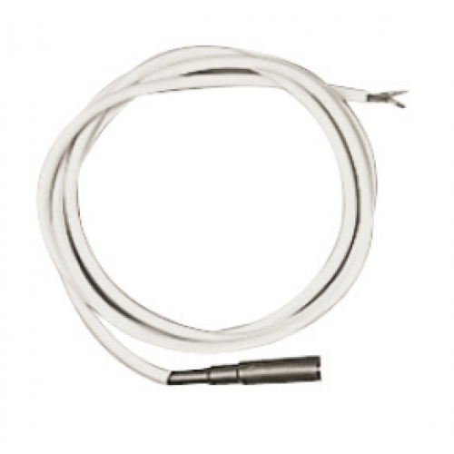
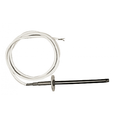
Temperature sensors
The sensors are connected with a 2-wire shielded cable regardless of polarity, the terminals in the sensor are only 2 and are not separately marked.
Checking sensor wiring
If the sensor is disconnected from the controller, it can be checked with an ohmmeter. At 25°C it has a resistance of 10.83 kΩ.
Types of temperature sensors
TGBK 330 - for air duct, IP67 protection
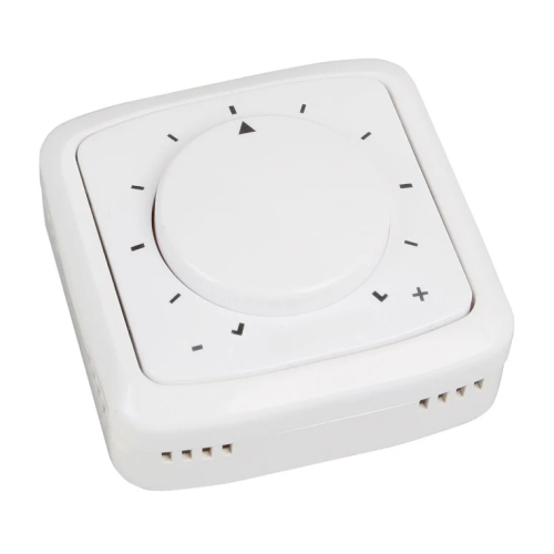
TGBR 430 - for space (room), IP30 protection, with optional control element for temperature adjustment
TGBA 130 - ground sensor, IP67 protection
For more details, please refer to the installation manual of temperature sensors or the catalogue.
Number of sensors connected to the controller
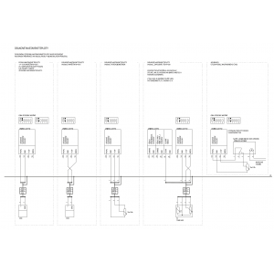
1, 2 or 3 sensors are connected to the controller. The main sensor must always be connected, the limiting sensor is connected in case of control to a constant room temperature. If the controller is used to control the output of a hot water heater, a frost sensor is also connected to the return pipe of the hot water circuit.
Main temperature sensor (S1)
This sensor can be placed in two positions according to the desired control function:
a) constant supply air temperature control - the sensor is placed in the supply branch of the air duct
b) constant room temperature control - the sensor is placed in the ventilated
room
Limiting Temperature Sensor (S2)
For constant room temperature control, a limiting temperature sensor is placed behind the heat exchanger, which limits the supply air temperature variation. In the case of electric heater control, it ensures that the temperature behind the heater is limited to 40°C (at higher temperatures the heater switches off).
In the case of constant supply air temperature control, the temperature limiting sensor is not connected.
Frost protection temperature sensor (S3)
The frost protection sensor is placed on the return line of the hot water heater water circuit, as close to the heat exchanger as possible. When controlling an electric heater, the frost protection sensor is not used - the terminals must be short-circuited.
Outputs
Signal for mixing valve actuator 24 V AC, max. 0.4 A, three-point output
Signal for electric heater power control 0 to 10 V, max. 10 mA output current
Signalling relay 24 V AC, 2 A
Switching contact, switches over in case of low temperature and failure of thermal protection of the electric heater
Failure relay 230 V AC, 5 A, 1250 VA / 150 W
Switches off in case of low temperature and failure of thermal protection of the electric heater
Mixing valve actuator
The mixing valve actuator of the hot water heat exchanger has a supply voltage of 24 VAC and is three-point controlled (signals open and close). The controller controls the actuator by pulses with a period of 4 s with an alternation that corresponds to the control deviation and the set parameters. A deviation of more than 20 °C produces a continuous output signal. If the deviation is less than 0,5 °C, the actuator is stationary.
The output to the actuator is protected by a fuse. Alternatively, it is possible to connect a servo drive controlled by a 0-10 V voltage - see diagram for details.
Rotation direction control:
The mixing node must be arranged according to the general instructions in the Mixing node section. The actuator must open when the frost sensor is disconnected.
Electric Heater Power Regulator
The electric heat exchanger is connected through a power regulator that converts a 0 to 10 V analog signal from the regulator output to a controlled power output for the heat exchanger connection.
Failure relay
This contact opens when the frost sensor is low and the thermal protection of the electric heater fails. In the case of an air handling unit with a hot water heat exchanger, the contact should be included in the fan switching circuit. In the case of an electric heat exchanger, it must not be included in the fan circuit.
Signal relay This contact will switch when an alarm is annunciated - low water temperature or overheating of the electric heat exchanger. It can be used to signal this condition.
External Temperature Setting
Remote Temperature Setting
If the controller is switched to the external setpoint mode, the temperature is set using a remote control - for example, a temperature sensor with a TGBR 430 controller can be used (only the temperature setpoint can also be used) or another potentiometer connected to the external temperature setting terminals. The temperature can be set in the range 0 to 30 °C.
External temperature setpoint shift
This input can be used to shift the setpoint temperature by ±15 °C.
A 5 V voltage or leaving the input free means zero temperature shift. A voltage of 10 V results in a setpoint shift of +15 °C, a voltage of 0 V results in a setpoint shift of -15 °C. The dependence is not linear.
The input can be used, for example, to attenuate the temperature (in combination with a switching clock).
Fan Clock
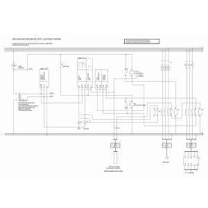
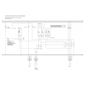
See the basic wiring diagram of the power section. This input switches the controller between the stopped operation state and the operating state. The input is normally coupled to the HVAC fan run.
Electric Heater Fault
See basic power section wiring diagram. A voltage-free opening contact in the emergency heat protection circuit of the electric heat exchanger is connected to this input. When it is opened, the alarm relays will trip and the ALARM light will illuminate. The emergency thermal protection alarm is reset by pressing the reset button on the controller panel (use a suitable object, e.g. match, skewer, etc.) or by interrupting the supply voltage to the controller. The emergency thermostat must be connected to the power supply circuit of the power exchanger, not just the controller terminals, and sometimes requires manual thermostat deblocking. When controlling a hot water heater, this input is shorted.
Description of controller functions
Setting the desired temperature (SETPOINT)
Set the desired temperature here. The operation of the controller varies according to the type of control (determined by installation and setting):
Constant supply air temperature control
The control temperature sensor measures the supply air temperature, the controller regulates the output of the corresponding heater so that the supply air temperature matches the set temperature. The CF and MIN settings have no meaning here. Control to constant room temperature The control temperature sensor measures the temperature in the ventilated space. If the measured temperature is greater than or equal to the set temperature, the supply air is reheated to the temperature set by the MIN knob. If the room is cooler, the air temperature is increased according to the CF setting.
Temperature increase = (difference between set and room temperature) x CF.
Types of control
Using the switches under the terminal cover, the type of control can be set. Important: The switch settings and the actual location of the temperature sensors must always correspond.
Constant supply air temperature control
The controller regulates the output of the respective heat exchanger so that the outlet air temperature matches the set temperature. The main sensor is placed in the supply branch of the air duct, the limiting sensor is not connected. The CF cascade factor must be set to 1 (or not applied).
Regulation to constant room temperature
The purpose of the control is to achieve the desired room temperature. Cascade control with minimum supply air temperature limitation is used. The main sensor is placed in the ventilated space, the limiting sensor is placed behind the heater in a location with sufficient air mixing. If the room temperature is greater than or equal to the setpoint, the controller will maintain the supply air temperature at the value set by the MIN control (set minimum supply air temperature). If the room temperature drops below the setpoint, the controller attempts to compensate by increasing the supply air temperature. The rate of supply air temperature increase is determined by the cascade factor CF. For example, if the space is 2°C below the set temperature and CF=5, the controller will supply air to the space at a temperature 10°C above the set temperature.
The cascade factor must be set to take into account the inertia of the controlled system so that there is no temperature oscillation. A smaller factor will cause greater system stability, a larger factor will cause faster correction of the temperature difference.
The minimum temperature should be selected with respect to the heat gains in the space so that the supply air can dissipate this heat. A high minimum temperature would make it impossible to correct the internal temperature downwards (the room would still be overheated), a low minimum temperature could cause a risk of air conditioning failure due to the danger of freezing of the heat exchanger.
Frost protection
If the temperature at the frost protection sensor drops below 10°C, the controller will start to permanently open the water valve. When the temperature drops below 5°C, the alarm and signal relay (if part of the fan circuit, the fan will be switched off) will change its state and the ALARM indicator will light up. The frost protection alarm is reset by pressing the RESET button on the controller panel (the button is below the panel level, use a suitable tool) or by interrupting the controller supply voltage.
Stop Mode
The controller enters this mode by disconnecting the fan run input. In this mode it tries to maintain 25°C at the frost sensor location (in case of hot water heat exchanger control). This function minimizes the risk of freezing (failure) and unpleasant cold drafts when the air handling unit is started. In the case of electric heating, the output to the electric heat exchanger is blocked in the stopped operation mode (the frost sensor input must be shorted)
Setting the type of control
The controller functions can be set using five switches (section 6 is without function) located under the cover of the lower left terminal block. To expose the cap, insert a suitable screwdriver (max. 3 mm wide) from above into the groove in the centre of the cap until the cap clicks and releases.
The type of control is set using switches 1, 3, 4 and 5.
Constant Supply Air Temperature Control
1 and 4 = OFF (slide switch position down)
3 and 5 = ON (slide switch position up)
Constant Room Temperature Control
1 and 4 = ON
3 and 5 = OFF
Temperature Setting
Setting on the controller
2 = ON
Remote Setting
2 = OFF
Local Temperature Setting
The temperature is set locally with the SETPOINT knob on the controller panel. It can be set in the range of 0 to 30 °C.
Cascade Factor
The cascade factor is set with the CF knob in the range of 1 to 15 according to the procedure described in the chapter Controlling for constant room temperature.
Minimum limit temperature
This parameter specifies the minimum supply air temperature for cascade control. It is set using the MIN knob in the range of 0 to 30 °C.
Connection of MaR elements
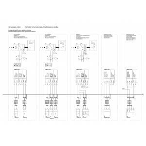
Mixing node
The figure shows the correct arrangement of the mixing node:
The mixing node must be located in the immediate vicinity of the heat exchanger. There should be a shunt in front of the mixing valve to maintain a constant pressure ratio on the primary side. The correct position of the mixing valve (tapered, vertical displacement) is determined by the installation. A cheaper and frequently used alternative to the mixing valve is the mixing (control) butterfly valve (ESBE). The correct position of the actuator and control shaft is set so that the notch on the control shaft is in the open position in position B, and in the closed position in position A (not AB). Once the control shaft is properly rotated, it may be necessary to rotate the scale plate on the mixing valve. Proper design and installation of the mixing node are critical to the resulting control function. If the mixing valve is oversized, it may be impossible to achieve the desired temperature stability.
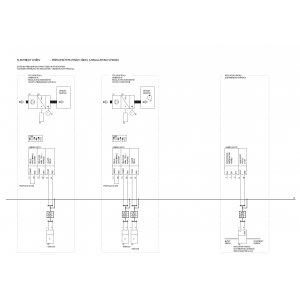
Connecting the Sensors
Connect the temperature sensors according to the diagrams in Chapter 8 using the recommended or equivalent cable type. The cable shield shall be terminated in the immediate vicinity of the wire connection terminals.
Fault message (ALARM)
This is not usually a controller fault, but only a response to hazardous operating conditions. The air handling unit is shut down. The alarm can only be reset after the cause of the alarm has been eliminated. Repeated occurrences of alarms must be resolved by a specialist.
For a hot water heater, the alarm indicates the risk of freezing and cracking of the heat exchanger (e.g. insufficient heating water supply may be the cause).
For an electric heater, the alarm indicates the risk of overheating or, in extreme cases, fire (e.g. This may be caused by an unmaintained filter and thus a reduced amount of incoming air)
Internal fuse
UNIREG and the output to the actuator is internally protected by a 500 mA tube fuse T, size 5x 20 mm. The fuse is accessible in the housing under the cover of the lower left terminal block, replacement is only possible with a type of the same value.
General and safety instructions
The device may only be used in the intended range of use, in perfect technically safe condition, all warnings in this installation manual must be observed. The safety circuits must not be disabled.
Electrical connection
The device is designed for installation in a switchboard. The power supply must meet the requirements for SELV type circuits, the connected circuits must meet the requirements for Class III insulation equipment. Wiring of the device may only be carried out by a person who complies with the legal regulations for working on electrical equipment. The applicable safety standards, in particular CSN 33 2000-4-41, must be observed. It is essential to check the wiring before starting up. The equipment must have been subjected to an initial inspection of the electrical equipment in accordance with ČSN 33 1500 and ČSN 33 2000-6-61 before it is put into operation.
Training of persons
Work on the equipment may be carried out by personnel with appropriate electrical qualifications who are also trained and familiar with the correct function of the components used and the air handling unit as a whole. In order to operate the equipment, the operator's personnel must be demonstrably trained.
Design changes to the equipment
No changes shall be made to the equipment without the written approval of the manufacturer.
Maintenance
Maintenance of the equipment is part of the maintenance of the entire switchgear. Maintenance includes checking the tightening of terminals, checking the functionality of the equipment in relation to the temperature measured by temperature sensors, etc. Particular attention should be paid to the safety circuits (e.g. capillary frost protection or thermal protection of the electric heater), including the correct response of the control system. Any faults found must be rectified immediately. These inspections are carried out at least once a year (or more frequently depending on local conditions) by an authorized professional service company.
In normal operation of the equipment, an occasional check of the condition of the equipment, as indicated by the controller's indicator lights, is sufficient.
WARNING! During any manipulation of the air handling unit (e.g. checking the fan belts or changing the filter), it is necessary to switch off the power supply to the entire cabinet with the main switch and secure against unexpected switching on!
Installation and Recovery
Mandatory Commissioning Tasks
- Verify proper power connection
- Verify all terminals are tightened
- Check operation of damper actuators and smooth operation of dampers
- Check mixing valve operation, correctly set the sense of rotation of its actuator (in the case of hot water heat exchanger control)
- pay special attention to the thermal protection circuit of the electric heater (in the case of electric heat exchanger control)
- according to the location of the control sensor and temperature selector, correctly set the DIP switches controller
- according to the nature of the HVAC unit, set the minimum limit temperature and cascading factor
- check the function of the entire switchboard and all connected elements
- perform an initial electrical inspection of the entire switchboard according to the instructions in the General and Safety Instructions chapter
- training of persons is necessary, who will be operating the equipment and to make a record of this
Electrical wiring of the equipment
The wiring of the entire equipment must follow in particular the safety and electromagnetic compatibility aspects as defined by the applicable standards.
The cables must be secured outside the controller against pulling out (e.g. by placing them in the wiring rail).
Protection against dangerous contact between live and inanimate parts of the controller is ensured by insulation class III and by using a SELV or PELV power supply.
The length of the connected cables should not exceed 30 m for shielded cables with a vertical overhang of up to 20 m.
Separation of safe and mains voltage circuits
The terminals of the UNIREG device are (or may be) connected to the safe (low) voltage, except for the terminals of the fault relay (terminals 11-12), which may be connected directly to the control circuit of 230 V contactors. This circuit shall be isolated from the safe voltage circuits as described in the following paragraph.
Safety separation
Separation in the control cabinet is practically possible:
- By spatial separation of conductors
- The safe voltage conductors, in addition to having basic insulation, must be contained in a non-metallic sheath (additional insulation - e.g. an insulating tube).
- The possibility of contact between circuits of different voltages when the conductor is released from the terminal must be considered. If contact could occur when the conductor is released, the conductors must be tied together at least in pairs or placed in an insulating tube. Only conductors of the same voltage group shall be bonded together. - It is not permitted to run circuits of different voltages together (e.g. sensor circuit and pump supply) in commonly used cable types.
Separation in terms of EMC
Cable routes of safe and mains voltage must be separated due to electromagnetic compatibility requirements.
- It is necessary to build 2 cable routes at a distance of at least 20-30 cm from each other, preferably with minimum crossing. A grounded metallic partition at the full height of the metallic grounded trough is also permissible.
Other EMC principles
If the main supply has a conductor cross-section smaller than 6 mm2, it is recommended to connect the controller to the grounding system with a conductor of at least 6 mm2 (copper) due to the impedance of the grounding conductor for the removal of RF interference. The cable shield is connected directly to the PE potential in the switchboard.
Certification - electrical safety and EMC
Safety:
According to EN 60730-1 +A1+A11+A12 (Automatic electrical control equipment for household and similar purposes. Part 1: General requirements)
Electromagnetic compatibility:
- Radiation according to EN 50081-1:1994 (Electromagnetic compatibility. General standard relating to radiation. Part one: Residential, commercial and light industrial environments)
- immunity according to EN 61000-6-2:2000 (Electromagnetic compatibility (EMC) - Part 6-2: Generic standards - Immunity for industrial environments)
Adherence to these instructions should not pose any safety, health or environmental risks in accordance with EC directives (CE marked). The same applies to other products used in the device or during installation. Consider the following warnings:
• Observe the safety instructions to prevent damage to the device or personal injury.
• The technical information in this manual must not be changed.
• It is forbidden to interfere with the motor of the device.
• In order for the device to comply with EC directives, the device must be connected to the mains in accordance with the applicable regulations.
• The device must be installed in such a way that under normal operating conditions it cannot come into contact with any moving part and / or live part.
• The device complies with the applicable regulations for the operation of electrical equipment.
• Always disconnect the device from the power supply before carrying out any work on it.
• Appropriate tools must be used when handling or maintaining the device.
• The device must only be used for the purposes for which it is intended.
• This appliance is not intended for use by children under 8 years of age and persons with reduced physical, sensory or mental capabilities, or lack of experience and knowledge, unless they have been given supervision or instruction concerning use of the appliance by a responsible person. The user must ensure that children do not play with the device. Cleaning and maintenance of the appliance must not be carried out by children without supervision.