Information
The distribution node is used to control the cooling water flow to MKW (IKW) water chillers. The nodes are designated ESUCH Cxx-Vyy A, where xx in the type designation indicates the pump type and yy indicates the "kVS" value of the distribution valve. The valve control is provided by a BELIMO actuator. It is supplied in version "A" with an analogue 0-10 V controlled actuator.
The external control system provides continuous control of the water chiller output by changing the cooling water flow to the water chiller (so-called quantitative control) using a 0-10 V signal. The water flowing through the node must be free of impurities, solid impurities and aggressive chemical substances that disturb copper, brass, stainless steel, zinc, plastics, rubber. The permitted operating parameters are as follows. v.
- maximum concentration of ethylene glycol 40%
- maximum concentration of propylene glycol 40%
- ambient temperature range at the installation site of the node 0 °C ÷ 50 °C
The minimum operating water pressure ensures that no air is drawn in through the bleeder valve, which must be mounted at the highest point of the water circuit.
When designing the location of the ESUCH node, we recommend that the following principles are observed:
- follow the manufacturer's instructions for the application of the water cooler
- the manifold node must always be mounted so that the pump motor shaft is in a horizontal position
- the manifold node must be in this position, to ensure that it can be vented at a later date
- when located in the ceiling, inspection and service access to the manifold and vent valve must be maintained
Sizes and Materials
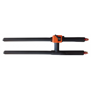
Manifolds are manufactured in a performance range of nine sizes, which vary by pump type, three-way valve size and connection pipe diameter. The cooling water connection is unified on 22 and 28 mm diameter copper pipe. The flow rate and pressure drop of the manifold is determined by the size of the control valve (kVS in the range of 0.6 to 16).
Design
The manifold is equipped with two ball valves at the inlet to ensure that the cooling circuit can be disconnected during repairs. On the water cooler connection side, the junction is fitted with flexible steel hoses to allow easy adjustment to the water cooler inlet spacing. The entire junction is thermally insulated with 13 mm thick Armaflex insulation. The Grundfos pump is fitted with an external insulation cover. A filter with a removable and cleanable filter insert is located between the inlet ball valve and the pump. The three-way valve is controlled by a BELIMO servo drive of type HT series. The distribution node is exclusively equipped with a servo drive HT 24-SR-T, which is designed for continuous control (control by analogue signal 0 to 10 V). The supply voltage of the HT 24-SR-T servo drive is AC/DC 24 V.
The ESUCH node is available in 2 versions:
- with pump - ESUCH Cxx Vyy A
- without pump - ESUCH C00 Vyy A
Regulation
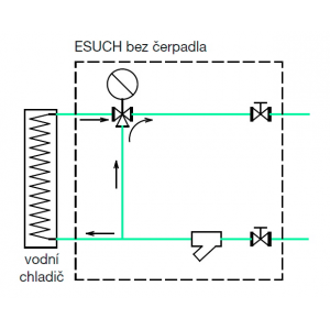
The distribution node is installed in front of the water cooler. The pump ensures the circulation of water through the water cooler when there is insufficient pressure potential in the central chilled water distribution system. When maximum water chiller capacity is required, all cooling water flows through the water chiller. In the case of a minimum chiller capacity requirement, the three-way valve section at the water outlet of the water chiller is closed and cooling water flows from the inlet through the three-way valve to the return (in this case the cooling water flow through the water chiller is 0 m3/h). When partial chiller output is required, part of the water is discharged to the water chiller and part of the water is returned to the return line of the chilled water supply.
Installation and Maintenance
The distribution node is connected to the chiller. The manifold shall never be subjected to stress or twisting of the connected piping. Distribution nodes should be mounted on separate hangers using heating sleeves on the wall, pipe or an auxiliary structure. When located below the soffit, inspection and service access to the junction must be maintained for easy cable connection and possible maintenance. When installing the node, the filter must be turned with the drip pan down. If the filter is not positioned correctly, there is a risk of increased clogging and blockage of the filter. Reduced filter patency or even impassability results in a significant reduction in cooler performance.
Particularly during test operation, the filter drain pan should be checked and cleaned. If the filter is frequently clogged, the entire cooling circuit must be cleaned. Even during normal operation, the filter must be checked regularly. When cleaning the filter, it is necessary to close all water paths to minimize water leakage from the system. Always install the distribution unit so that air can escape to the water cooler vent points or the entire cooling circuit.
The manifold must always be mounted with the pump motor shaft in a horizontal position.
After the cooling water distribution system has been watered, the circulator must be vented according to the manufacturer's (Grundfos) instructions. On each pump, the speed (pump characteristics) can be switched by means of a button on the front.
Information
In case of a request for larger valve dimensions (kVS = 25 or 30) please contact the technical department of ELEKTRODESIGN ventilators, s.r.o. For these larger dimensions, it is possible to supply the three-way valve and the pump separately in flanged design for the purpose of installation in the cooling water distribution system by the installer. The nodes of these larger dimensions can no longer be attached to the air handling unit.

 Share on Facebook
 Tweet
Tweet Send email