

 Share on Facebook
 Tweet
Tweet Send email
Information
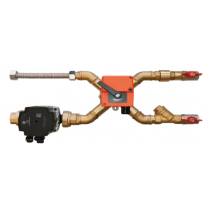
The mixing node is used to control the flow of heating water to MBW (IBW) water heaters up to a heating capacity of 120 kW. The designation ESU Cxx - Vyy, where xx in the type character indicates the pump type, yy indicates the Kvs value of the mixing valve. The control is provided by a BELIMO servomotor. Version A is with a 0-10 V analogue controlled servo drive, it is mainly intended for control from a customer control system. Version B is with a three-point actuator, designed for control by a Digireg® controller.
In addition to power control, the control system provides freeze protection for the water heater. Power control is provided by mixing the inlet water with the return water at a constant water flow rate. The mixing node, in conjunction with other system components, provides freeze protection for the water heater. The water flowing through the node must not contain impurities, solid impurities and aggressive chemical substances that disturb copper, brass, stainless steel, zinc, plastics, rubber. The maximum permissible operating parameters of the heating water are as follows:
- maximum medium temperature +110 ˚C
- minimum medium temperature +2 ˚C
- maximum water pressure 1 MPa
- minimum water pressure 20 kPa
- relative humidity 90% non-condensing environment
The temperature of the water must not fall below the ambient air temperature during operation, as there is a risk of condensation in the pump motor. The minimum operating water pressure ensures that no air is drawn in through the bleeder valve, which must be fitted at the highest point of the water circuit.
When designing the location of the mixing node, we recommend the following principles:
- follow the manufacturer's instructions for VO application
- the mixing node must always be fixed so that the pump motor shaft is in a horizontal position!
- the mixing node must be in a position to ensure that it is vented
- when located in a ceiling, inspection and service access to the mixing node and vent valve must be maintained
Sizes and Materials
Mixing nodes are manufactured in a power range of ten sizes, varying in pump type, three-way valve size, actuator type and connection pipe diameter. The heating water connection is unified to 3/4'' and 1'' diameter copper piping. The flow rate and pressure drop of the mixing node is determined by the pump size and the size of the control valve (Kv range 0.6 to 16).
Conduct
The mixing node is equipped with two ball valves at the inlet to provide the ability to disconnect the heating or cooling circuit during repairs. A filter is included upstream of the mixer. The four-way and three-way mixer is controlled by a BELIMO servo motor of the HT series. A pump is located behind the mixer. The type designation of the mixing node distinguishes the method of control of the servomotor by the last letter (A, B). The letter A indicates that the mixing unit is equipped with an HT 24-SR-T servo drive, which is designed for continuous control (control by an analogue voltage signal from 0 to 10 V). The letter B indicates that the node is designed to be controlled by a Digireg® controller and is equipped with an HT 24-3-S servo drive with three-point 24 V control. The maximum output is specified for a water temperature gradient of 80/60 ˚C.
Regulation
The mixing node is installed in front of the water heater. The pump ensures the circulation of water in the heater. The mixing valve, operated by a servo drive, provides power control by mixing the heater return water and the heating water. When the control system is set to full heat output, all water flows in a large circuit, i.e. from the boiler through the primary circulation pump to the mixing node, passes through the filter, valve, SU pump, water heater and returns to the boiler via the return line to the heating water header.
When the heater output is reduced, the valve begins to pass only a portion of the water from the source, thus steadily reducing the temperature of the water flowing through the heater. If no heating output is required, only water flows in the heater circuit, i.e. the valve passes the entire flow of water from the return through the pump to the heat exchanger. A four-way valve is used to ensure that the water flow in the boiler circuit is not completely stopped during control. The pump in the mixing node only overcomes the pressure losses of the heater circuit (i.e. the VO heater and all elements in the mixing node). The boiler circuit pump must therefore be sized to cover all pressure losses up to the mixing node (of the entire boiler circuit) and at the nominal water flow rate that was determined in the design of the water heater.
For mixing nodes with Kv up to 4.0, a three-way valve is used. It is recommended that a bypass be installed upstream of the mixing node to provide flow to the boiler even when the mixing node is closed. With a bypass installed, the pump flow to the boiler is not affected and the bypass also prevents the water in the boiler circuit from cooling.
Installation and Maintenance
The mixing node is connected to the heater. The mixing junction must never be subjected to stress and twisting of the connected pipe. The mixing nodes should be mounted on separate hangers using heater clamps on the wall, pipe or an auxiliary structure. When located below the soffit, inspection and service access to the mixing node must be maintained for easy cable connection. The filter requires regular inspection, maintenance and cleaning. When installing the node, the filter must be turned with the strainer down. Improper positioning can result in increased clogging and clogging of the filter. Reduced filter patency or even impassability results in a significant reduction in heater performance and increases the risk of heater freeze-up.
Primarily during the test operation, it is necessary to check and clean the drain tank. If the filter is frequently clogged, the entire heating circuit must be cleaned. Even during normal operation of the plant, the filter must be checked regularly. When cleaning the filter, it is necessary to close all water paths to minimize water leakage from the system. The mixing node must always be installed so that air can escape to the heater vent or boiler circuit vent points.
The mixing node must be mounted so that the pump motor shaft is in a horizontal position. After watering the system, the circulator must be vented according to the manufacturer's (Grundfos) instructions. The required pump speed is indicated for each mixing node. This is set by a plastic rotary wheel on the pump during installation. When connecting the mixing unit, the correct setting of the valve and actuator must be checked. With the mixing unit assembled, the position of the internal segment of the mixer can be recognised by the fitting on the face of the extension shaft. The perpendicular to the seating face of a three-way valve points to the axis of the inner segment, while that of a four-way valve points to the axis of the inner segment.
For the three-way valve version, the following procedure is followed. Of the three paths, the valve always closes the path to which the bevelled face on the valve shaft points. In the case of an assembled mixing unit, the setting can be distinguished by the notch on the face of the shaft extension. The notch always points towards the closed waterway. For the four-way valve version, the following procedure is followed. Of the four paths, the valve always has the path between which the notch on the face of the actuator shaft points closed.
Information
The mixing node cannot be used for flow control in cold water systems. We recommend the use of ESUCH nodes to regulate the output of water chillers.